Computer Vision for Robotics
TL;DR
In this lab we accomplished a lot! We used OpenCV to be able to read and ID apriltags which we then used to help move the Duckiebot using lane following and landmark recognition. We also utilized RViz to view where the Duckiebot thought it was in the robot frame compared to the world frame as well visualize the previous apriltag detections.
Part 1
Computer Vision
Below you can see a video of the Duckiebot detecting the apriltags. When this first started working, it was incredibly cool to see!
What does the apriltag library return to you for determining its position?
The apriltag library returns an AprilTag object for us! This is incredibly helpful since we are able to use commands like apriltag.corners to help draw the bounding box of the image.
Which directions do the X, Y, Z values of your detection increase / decrease?
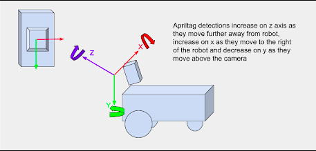
As stated in the above picture, apriltag detections will increase on the Z and X axis as they move in the positive direction. apriltag detections will decrease as they move in the negative direction on the Y axis.
What frame orientation does the apriltag use?
The camera frame is a translation and rotations away from the base of the robot frame so things change a little differently.
Skimming over some of the nuance of the camera being pointed down a bit, as the robot moves towards positive X in the robot frame, the apriltag gets closer - or the position in Z in the camera frame decreases.
If the robot rotates right, the apriltag detection will move towards negative x in the robot frame and vice-versa
The frame orientation can be found using the right hand rule. Utilizing the RHR, we are able to see a frame orientation similar to Fig.1
Why are detections from far away prone to error?
Detections from far away can be prone to error due to a few reasons:
- The angle of the camera: Since the camera is tilted down, some distortion can occur when trying to detect tags
- The field of view: With a wide field of view an image can look distorted when compared to a smaller FOV
- The physical camera: The physical camera equipped on the Duckiebot is not the best quality. It also has a slight fisheye lens which can cause added distortion
Why may you want to limit the rate of detections?
Since our Duckiebot is not equipped with very much onboard memory, it can get easily overloaded by trying to detect many objects in a small period of time. By limiting the number of detections, we can increase our operating efficeny and also speed up subsequent detections.
Part 2
Lane Following
Below you can see a video of the Duckiebot utilizing the PID controller and lane following American driver style.
Below you can see a video of the Duckiebot utilizing the PID controller and lane following English driver style.
For both of the above videos, there are a few subtlties to take note of:
- A vertical blue line down the centre of the screen to visualize the centre of the camera on the Duckiebot
- Green rectangles to track the closest lane segment. If two rectangles are present, the closest one is ignored
- A green line connecting the green square to the vertical blue line to visualize approximately how far off we are from centre
- A red dot rapidly moving around the screen to visualize how much rotation the Duckiebot must make to stay on the correct side of the road
What is the error for your PID controller?
This error is found by the following general equation: \(\begin{equation} error = (x + (sizeratio*y)) - goal) * pixelscale \end{equation}\)
where:
- \(x\) is the left most side of the closest dotted line
- \(y\) is the top of closest dotted line divided by two
- \(sizeratio\) handles distance distortion. It creates a linear function describing how close the dotted line is vs. how close the Duckiebot should be to it. This addresses the vanishing point problem
- \(goal\) is where the bot wants to be. Represented by a blue vertical line in the image
- \(pixelscale\) scales the error down to account for large error in pixels realative to a small error in angle
If your proportional controller did not work well alone, what could have caused this?
For our purposes a proportional controller worked well. If our system contained momentum, this could have caused overshoot. However, adding a derivative term and accounting for derivative kick could solve the momentum problem.
Does the D term help your controller logic? Why or why not?
Currently it does not help our controller since we did not have time to use it. Since our system does not consider a force like momentum, the P term is more than sufficent.
Why or why not was the I term useful for your robot?
While we did not implement the I term into this project it could have potentially been useful. Since the I term tries to compensate for error over time this could be useful when there is some error in the wheel encoders or slippage on the mat. If we did consider using an I term, we would also have to be wary of integral windup. To combat this, we would limit how large the I term could be.
Part 3
Localization using Sensor Fusion
Below you can see view from RViz as we do a lap around the track. The camera feed, odometry frame and static apriltag frame is shown. In this video, the moving object is our Duckiebot being controlled manually. The static objects shown are the apriltags in our world frame.
Where did your odometry seem to drift the most? Why would that be?
The most drift was seen when turning. The necessity for encoder precision is maximized in the turns since small errors can compound and cause large drift.
Did adding the landmarks make it easier to understand where and when the odometry drifted?
Adding the landmarks made it significantly easier! Being able to visualize where the robot is in real-time is very beneficial.
Show the generated transform tree graph, what is the root/parent frame?
There are currently two root frames - the first being the “{robot_name}/WorldFrame” frame that we created for the odometry and apriltag locations. The second was the “{robot_name} footprint” frame that contained all of the components of the bot are children of. It made sense to set the parent of the footprint frame to be the odometry frame, since we then would be able to visualize all components of the robot relative to the apriltag locations.
Move the wheels and make note of which join is moving. What type of joint is this?
To determine this, first we set footprint’s parent frame to be the odometry frame. For some time we tried to figure out how to connect the footprint of the bot to the odometry frame so the bot is placed where it perceived itself to be in the world. Using static transforms (similar to the apriltags) made this job possible. Plus, we use this same method further on! Being able to utilize all of this helped us to find that almost every joint type is fixed but the wheel joints are continuous.
You may notice that the wheel frames rotate when you rotate the wheels, but the frames never move from the origin? Even if you launch your odometry node the Duckiebot’s frames do not move. Why is that?
This was due to the two root nodes. We could set RViz to show the footprint of the Duckiebot OR show the WorldFrame with the odometry node. We need to connect the footprint to the odometry node for this to link properly.
What should the translation and rotation be from the odometry child to robot parent frame? In what situation would you have to use something different?
In this case, we want to use a translation of $(0,0,0)$ and a rotation of $(0,0,0)$. The odometry node shows precisely where the bot thinks it is, so no rotation or translation is needed. For example, we would need a translation or rotation if the odometry node was publishing the robot frame 90° off of expected.
After creating this link generate a new transform tree graph. What is the new root/parent frame for your environment?
The new root is just footprint. The key difference here is that the WorldFrame, apriltags, and odometry node are not appearing as a separate tree. We understand it to be that the “tf2_tools view_frames.py” script is hardcoded to assume the root is footprint, so even though footprint now has a parent odometry_node, it is not shown.
Can a frame have two parents? What is your reasoning for this?
No. The child frame needs to be positioned relative to the parent. If there are two parents that have two different positions, what does it mean to be $(+0.5, +0.5)$ transformed from both parents? This would give an inconclusive result or a bad coordinate. However, a parent can have multiple children; there’s no issue having multiple children reference a single parent’s location.
Can an environment have more than one parent/root frame?
It can, but it is highly recommended not to. Issue visualizing in RViz will occur as well as issues in testing and debugging the code.
Show the newly generated transform tree graph, what is the new root/parent frame?
The new parent frame shown on the transform tree graph is footprint - but in reality the root is “WorldFrame”. You can imagine just drawing a connection between “odometry” and “footprint” in Fig.3 - this is the true new tree.
Below you can see a video of the Duckiebot moving around the world frame with all robot frames attached to the moving odometry frame. Apriltag detections are also shown in the camera feed and visualized in RViz.
How far off are your detections from the static ground truth?
As seen in Vid.5, our detections are not incredibly accurate. Being able to see the physical location of the apriltags on the camera as well as the perceived location on RViz lets us know we have a bit of work to do on detections
What are two factors that could cause this error?
- The code to convert the 2d bounding box + depth to the 3d coordinate from the camera doesn’t account for distortion of the lens.
- Inaccuracies converting from the camera frame such as not accounting for camera being pointed just slightly down.
In the future we will add a video here of the Duckiebot moving around the world using lane following. Our sensor fusion node attempts to teleport the robot if an apriltag is found and to use odometry if no apriltag is detected. Our goal is to finish as close to the start as possible.
Is this a perfect system?
While this isn’t a perfect system, it is not bad. By using apriltag teleportation with a combination of dead reckoning and computer vision, we can get a fairly good lane following system. There are some definite improvements and tweaks we hope to make in the future.
What are the causes for some of the errors?
Some causes for the error include:
- Memory usage on the Duckiebot: In some scenarios, the Duckiebot seems to get a little bit overloaded and not have enough processing power to compute all the commands given to it at one time. When running manual control + RViz, we noticed some significant delay.
- Human tuning: Since we are tuning some constants by hand/inspection, the values are not optimal. Possibly by using machine learning we could fix this problem.
- Unaccounted distortion on camera: This can cause inaccuracies with our apriltag detections and our lane following.
What other approaches could you use to improve localization?
To improve localization we could:
- Use multiple sensors or improved sensors. By using signals like GPS we can have a more accurate reading of where we are
- Use machine learning. By training our bot we can have it better estimate it’s position
- Combination approach. By using a combination of improved sensors, machine learning, better data etc we can improve our localization by a large magnitude.